


.jpg)






.png)







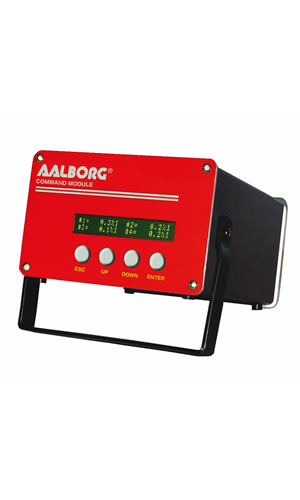
SDPROC Microprocessor Driven Command Module
SDPROC Microprocessor Driven Command Module
Aalborg Instruments & Controls
Description
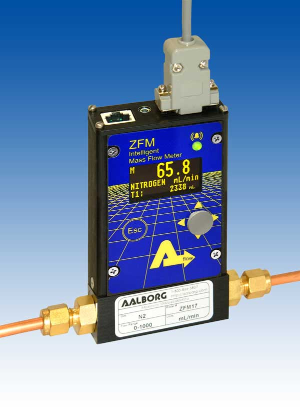
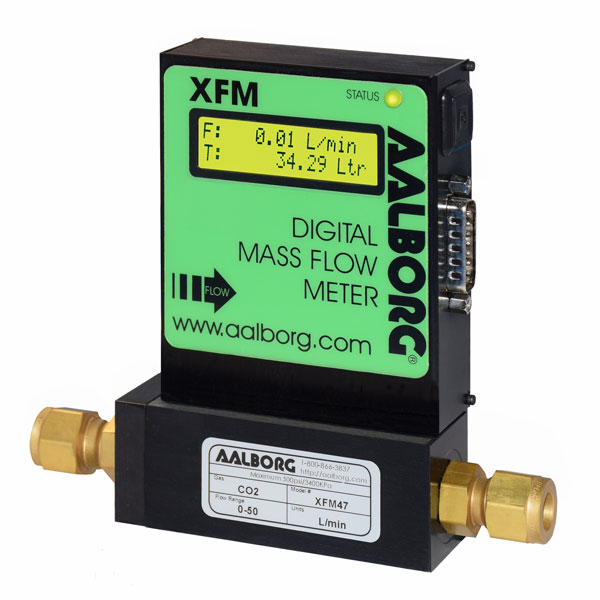
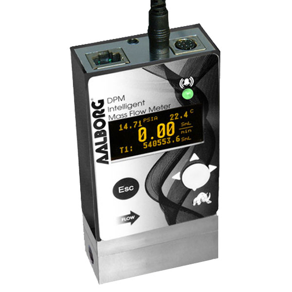
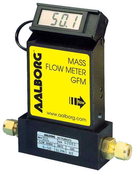
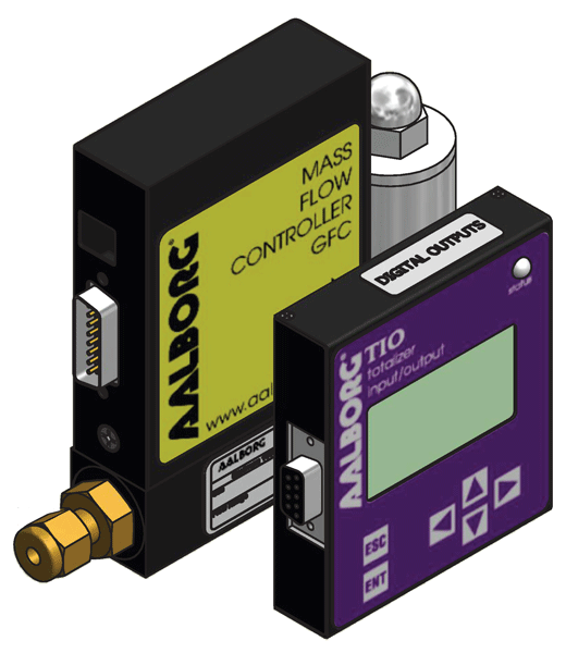
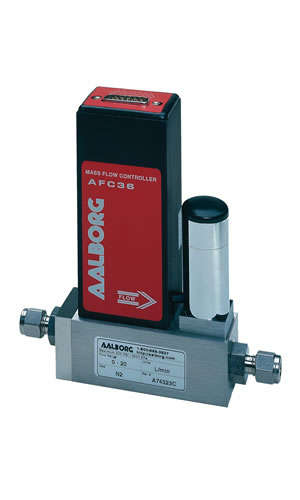
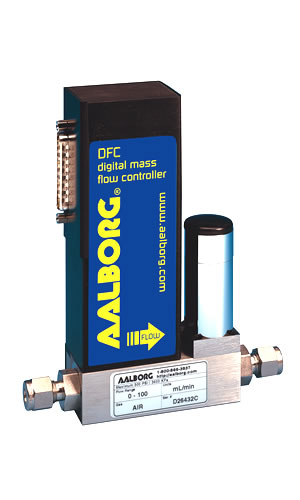
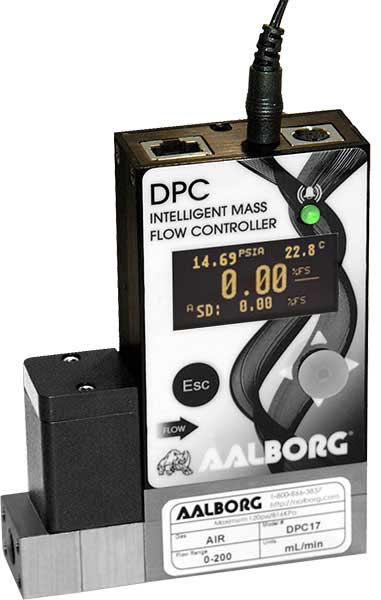
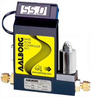
Microprocessor driven digital Command Modules are used in conjunction with any analog or digital mass flow meters or controllers with 0-5 Vdc input /output signals.
ENGINEERING UNITS
The flow set points, measured gas flow and associated totalizer data are scaled directly in engineering units via front panel keypad, RS-232 or Ethernet interface. The following units of measure are supported: %F.S., SLPM, SLPH, SCCM, SCCH, SCFM, SCFH, SCMM, SCMH, LBPM, LBPH, GRPM, GRPH.
USER SELECTABLE REFERENCE FOR SET POINT
The INTERNAL, EXTERNAL, PROGRAM refers to the point of origin for the Set Point signal. In Internal reference mode, the user sets the control signal with SDPROC controls (via front panel keypad, RS-232 or Ethernet interface).In EXTERNAL REFERENCE MODE, the user sets the control signal from a remote location (via the DATA IN/OUT 25-pin "D"-connector on the rear panel).In PROGRAM MODE the set point signal will be driven by user's custom program stored in the EEPROM. There are three Program modes: BATCH, TIMER and RATIO*.*RATIO mode not available for one channel module.
PROGRAMMABLE BATCH FLOW CONTROL
The Batch Flow Control allows execution of custom, user preset program of up to sixteen steps. During execution of the program the user can activate or deactivate the LOOP mode. Various flow configurations may be preprogrammed: ramping, pulsing, linearized increasing and/or decreasing of the flow.
PROGRAMMABLE TIMER FLOW CONTROL
The Timer Flow Control allows execution of custom, user preset program of up to 96 steps. Each step can be preprogrammed for a particular date, time, and set point value. Every step has two fields: starting date, time and set point in % F.S.
RATIO FLOW CONTROL
The Ratio Flow allows controlling flow of the mixture of up to four different gases (for 4 channel Command Module) with preset values of the ratio in % for each channel. The flow rate of the mixture can be incremented or decremented by changing the set point of the master channel #1.
FLOW ALARMS
High and Low gas flow ALARM limits can be preprogrammed for each channel. ALARM conditions become true when the difference between current readings and installed set points are equal or more than corresponding values of high and low alarm levels. Alarm action can be assigned with preset delay interval (0-3600 seconds) to one of the following:
- Contact closer (separate for High and Low alarm)
- Buzzer Audible Signal
- Valve shut down (Close)
TOTALIZER
The total volume of the gas is calculated by integrating the actual gas flow rate with respect to time. Both keypad menu and digital interface commands are provided to:
- Set the totalizer to ZERO
- Start the totalizer at a preset flow
- Assign action at a preset total volume
- Start/Stop totalizing the flow
- Read totalizer
Totalizer conditions become true, when the totalizer, and the "Stop at Total" volumes are equal. Totalizer action can be assigned to one of the following:
- Contact closer
- Buzzer audible signal
- Valve shut down (Close)
CONTACT CLOSURES
Two sets of dry contact relay outputs for each channel are provided to actuate user supplied equipment. The relays can be assigned to switch when a specified event occurs (e.g. when a low or high flow alarm limit is exceeded or when the totalizer reaches a specified value).
Environmental (per IEC 664): Installation Level II; Pollution degree II
Power Supply: 85 to 240 VAC (47 to 440 Hz); 120 to 370 VDC 2A max.
Fuse: 2A on input power line
Display: 24x2 LCD dot matrix with backlight; 24x2 Vacuum Fluorescent display optional
ADC/DAC Resolution: 12 bits (0.025%)
Communication Standard: RS-232 9600 baud rate, 8 bits, two stop bits, no parity (8,2,N)
Optional: Ethernet TCP/IP (HTML Server or TELNET Console)
Dimensions: length: 7.75" (19.5 cm), width: 6.75" (17 cm), height: 4.5" (11cm)
Weight: 4.5 lbs (2 kg)
Interface Cable: Flat cable with male 15-pin D connector and female 15-pin D connector on the ends is standard. Optional round shielded cable is available with male/female 15-pin D connector ends. [Cable length may not exceed 9.5 feet (3 meters)]
Data Port and Relay Cable: Optional shielded cable with male 25-pin "D" connector to connect to command module data and relay ports. [Cable length may not exceed 9.5 feet (3 meters)]





.png)